Blog

Why Do Air Compressor Parts Fail?

Why Do Air Compressor Parts Fail?

Air compressor parts rarely fail without warning. A hot bearing, cracked belt, or wet filter element often tells part of the story. The harder question is why the same trouble returns after replacement. In many shops, one defective component is not the whole explanation. Heat, dust, moisture, poor lubrication, vibration, and excessive cycling can combine. Even a correctly installed seal wears quickly when pressure and temperature exceed its working range. Small clues matter. A rising discharge temperature or an oil film near a fitting may look minor, but both deserve investigation.

Compressed-air specialist Ron Marshall’s work supports a practical takeaway: “Trace the operating conditions, not only the failed component.” This is a paraphrase, not a verbatim quotation. That distinction matters when maintenance decisions depend on evidence. This introduction explores how operating conditions, installation choices, and missed service intervals affect air compressor parts such as valves, bearings, seals, filters, and separators. It also considers warning signs technicians can observe, from unusual noise to pressure swings and oil carryover. Replacing a damaged part may restore operation for a while. It may not fix the cause. Sometimes, the first diagnosis is wrong. Careful inspection, operating records, and manufacturer guidance help separate normal wear from a recurring system problem.
Why Do Air Compressor Parts Fail?

Which Compressor Parts Fail First: Bearings, Seals, Valves, and Rotors

Why Do Air Compressor Parts Fail?

Which Compressor Parts Fail First: Bearings, Seals, Valves, and Rotors

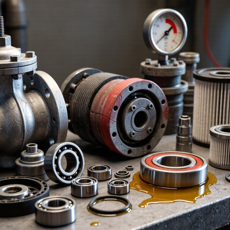
Bearings often show trouble through rising vibration, rumbling, or unusual heat. Poor lubrication, dirt, and misalignment can accelerate wear. Seals may harden or crack when exposed to heat, oil breakdown, or repeated pressure changes. A small leak can gradually reduce output, even when the compressor still sounds normal. Valves can stick when deposits build up, while worn springs may cause irregular pressure. These symptoms vary by compressor design and operating conditions; there is no universal failure order.

Rotor damage is often less common, but it can be costly. Excessive heat, contamination, or worn bearings may disturb rotor clearances and cause contact. Listen for changes, but do not diagnose from sound alone. Diagnosis is rarely tidy; several worn parts can produce similar symptoms, and a quick guess can send repairs in the wrong direction.

Tips: Check operating temperature, vibration, pressure, and visible leaks regularly. Keep maintenance records and compare readings over time. Follow the equipment manual for inspection intervals and lubricant requirements. If symptoms persist, have a qualified technician inspect the unit before replacing parts.

How Contamination Causes Wear: ISO 8573-1 Rates 3 Airborne Contaminants

Air compressor parts can wear long before they look damaged. ISO 8573-1:2010 classifies compressed-air purity by three contaminants: particles, water, and total oil. Its Class 1 limits are demanding: no more than 20 particles per cubic metre in the 0.1–0.5 μm range, a pressure dew point of −70°C or lower, and total oil at or below 0.01 mg/m³. These figures are purity limits, not guarantees that every machine needs Class 1 air. The right class depends on the equipment and process.

Particles act like fine grit. They score valve seats and abrade seals; a clogged intake filter can also restrict airflow. Water can collect in low points, wash lubricant from surfaces, and encourage corrosion. Oil aerosols may leave sticky deposits on control valves and sensors. A small oversight matters. ISO 8573-1 gives a shared way to specify and verify air quality, while ISO 8573 test methods describe how contaminants are measured. A dew-point reading alone cannot reveal particles or oil. And a filter’s appearance can mislead. Check differential pressure, drain function, and sampling results at the point of use; otherwise, clean air at the compressor may still arrive contaminated at the component.

Why Do Air Compressor Parts Fail? — How Contamination Causes Wear

ISO 8573-1 Class 3 limits for three compressed-air contaminants and their common effects on equipment.

Contaminant and measurement ISO 8573-1 Class 3 limit How it causes wear or failure Parts at risk and possible signs Typical control measures
Solid particles
0.1–0.5 μm
No more than 90,000 particles per m³ Fine particles can enter close-clearance areas, contribute to abrasive wear, and contaminate lubricants or sensitive processes. Valves, bearings, seals, pneumatic components, and downstream instruments; possible signs include sticking valves and accelerated seal wear. Use appropriately selected particulate filtration, maintain filters, and check for particle ingress from the intake or distribution system.
Solid particles
0.5–1.0 μm
No more than 1,000 particles per m³ Particles can abrade moving surfaces and interfere with small clearances, especially where air is used in precision controls. Control valves, actuators, regulators, and air-operated tools; possible signs include sluggish operation and scoring. Install filtration suitable for the required air-quality class and replace or service filter elements according to condition and pressure drop.
Solid particles
1.0–5.0 μm
No more than 10 particles per m³ Larger particles can cause direct abrasion, block small passages, or damage sealing surfaces. Valve seats, seals, orifices, and tool components; possible signs include leakage, blockage, and uneven wear. Use suitable particulate filters and remove accumulated condensate and debris from the system during maintenance.
Water
Pressure dew point
−20°C or lower Excess moisture can condense in pipes and equipment, promoting corrosion, washing away lubricant, and impairing pneumatic operation. Pipes, receivers, valves, cylinders, and tools; possible signs include corrosion, water carryover, sticking, or freeze-ups in cold conditions. Use drying appropriate to the required dew point, drain condensate, and monitor dew point at the relevant operating pressure.
Total oil
Liquid, aerosol, and vapor
No more than 1 mg/m³ Oil contamination can foul surfaces, deposit in air passages, affect seals and coatings, and compromise processes that require clean air. Filters, valves, regulators, seals, and downstream equipment; possible signs include sticky deposits, contamination, and impaired component response. Use oil-removal treatment appropriate to the application, monitor filter condition, and identify oil carryover or vapor sources.

Reading the limits: ISO 8573-1 classifies compressed-air purity at a specified measurement point. The particle limits are counts per cubic metre in each stated size range; the water limit is pressure dew point; and the oil limit is total oil concentration. The air-quality class required depends on the application, and filtration or drying should be selected accordingly.

How Heat Ages Lubricants: A 10°C Rise Can Halve Oil Life

An air compressor may run smoothly while its lubricant quietly loses protection. A common maintenance rule says oil life can fall by about half for every 10°C rise in operating temperature. Treat this as a useful warning, not a guarantee; oil formulation, workload, contamination, and measurement location all matter. Heat speeds oxidation. Oil can thicken, lose protective additives, and leave varnish near valves or narrow oil passages. Dark oil or a burnt smell deserves attention, though appearance alone cannot diagnose its condition.

Measure temperature where the compressor maker specifies, and compare readings over time. A room thermometer can miss heat building inside the oil sump or around the discharge line. Check cooling fins for dust, confirm ventilation is not blocked, and inspect for unusual noise or rising power use.

These small clues may appear before a clear breakdown. Oil analysis can reveal oxidation and contamination more reliably than color, especially when service intervals are uncertain.

It is tempting to blame every failure on overdue oil; that is too simple. A clogged cooler, frequent starts, or a failing thermostat may be the real heat source. Keep records, but question them when operating conditions change.

How Pressure, Cycling, and Vibration Accelerate Mechanical Fatigue

Why Do Air Compressor Parts Fail?

Pressure, cycling, and vibration slowly wear down an air compressor’s moving parts. Each pressure rise loads seals, valves, and cylinder components. If pressure repeatedly exceeds the unit’s rated range, small cracks or leaks may develop sooner. Heat adds stress, especially when airflow is restricted or cooling surfaces are dusty. A compressor may still run while its performance quietly declines.

Frequent starts and stops create repeated expansion and contraction. Over time, this can loosen fasteners and fatigue electrical or mechanical connections. Vibration from misalignment, worn bearings, or an unstable mounting surface can make the damage worse. A faint rattle matters. But its source is not always obvious; guessing can lead to the wrong repair. Check operating pressure, start frequency, and maintenance records alongside the sound. Follow the equipment manual, and have a qualified technician inspect persistent vibration or unusual wear.

Tips: Keep cooling vents clear, secure the compressor on a stable surface, and avoid unnecessary rapid cycling. Record changes in noise and pressure. Small notes can reveal a pattern. Don’t overtighten fasteners or adjust pressure settings without checking the manual.

Why Air Compressor Parts Fail: Fatigue-Cycle Exposure

Calculated cycle counts over 1,000 operating hours. Pressure-cycling rates and vibration frequencies are scenario inputs, not measured field data.

Vibration can create many more stress cycles than pressure loading. Cycle count alone does not determine fatigue life: stress amplitude, material, temperature, and component condition also matter.

How Inspection Tracks Failure: Monitor Temperature, Vibration, and Pressure

Why Do Air Compressor Parts Fail?

A failing compressor often gives warning before it stops. Track discharge temperature, vibration, and pressure together; one reading rarely tells the whole story. A rising discharge temperature may point to restricted cooling, poor ventilation, or lubrication trouble. Increasing vibration can signal looseness, misalignment, or bearing wear. Compare readings with the machine’s normal operating baseline, not a generic limit. ISO 20816-3 evaluates vibration by machine type and operating conditions, so context matters.

Pressure trends add another clue. Record inlet and outlet pressure during steady demand, and note sudden drops or slow recovery. A pressure dip alone is not a diagnosis. It may come from a clogged filter, a leak, or changing system demand. The U.S. Department of Energy’s Improving Compressed Air System Performance guide reports that leaks can waste 20–30% of compressor output in poorly maintained systems. That figure is a warning, not a prediction for every plant. Data also needs careful interpretation; a sensor can drift, and I would not trust one unusual reading without a repeat check.

Tips: Log readings at the same points and under similar loads. Inspect hot spots with a temperature probe, listen for new rattles, and check pressure gauges against a reference. Flag repeated changes, even small ones. A simple trend chart can catch trouble earlier than a monthly snapshot.