
24 Hour ServiceAn LED linear module is a long, narrow lighting assembly designed to produce an even line of light. It typically contains LEDs mounted on a circuit board, with electrical connections and, in some designs, optical components. The module may sit inside an aluminum channel or a complete luminaire. A diffuser can soften visible points of light, while the housing helps manage heat. Small details matter.
The term is not perfectly standardized. Some suppliers use “LED linear module” for the light-engine board alone; others mean a board combined with optics or mounting parts. Check the product drawing, dimensions, voltage, current, and compatible driver before choosing one. Also review the stated operating temperature and installation guidance. A module that fits the channel may still perform poorly if heat cannot escape or the driver is unsuitable.
In practical use, these modules appear in offices, shops, kitchens, and display cases, where continuous illumination can be more useful than isolated light spots. For example, a slim module beneath a cabinet can brighten a countertop without taking up much space. Results depend on layout, diffuser, and installation quality. Not every linear module produces perfectly uniform light, and a bright specification alone tells only part of the story. Understanding its construction and limits makes comparison more reliable.
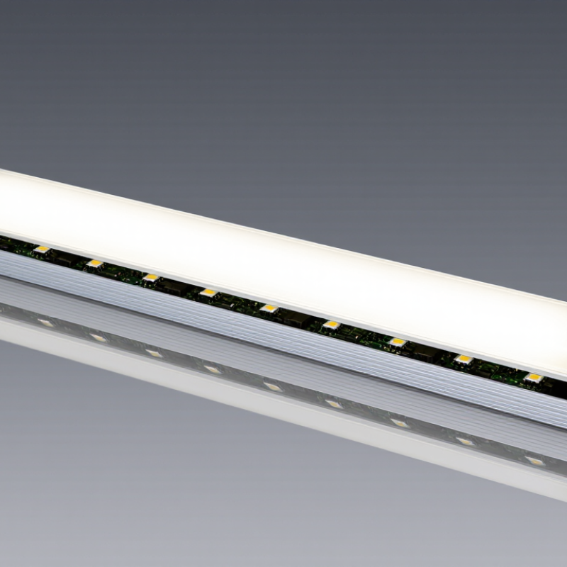
An LED linear module is a row-shaped light source containing LEDs on a circuit board, with electrical connections and supporting components. Under IEC 62031, it is treated as an LED module for general lighting, not automatically as a complete lamp or luminaire. The standard sets safety requirements for the module itself. It does not establish a universal efficiency level or prove that every finished fixture is safe.
IEC 62031:2018, including Amendment 1:2021, addresses risks such as electric shock, insulation failure, and excessive temperatures. Testing may examine construction, electrical protection, and heating under specified conditions. Details matter. A module that passes alone can still be used in a poorly designed luminaire. Fit, heat transfer, wiring, and the matched controlgear all affect the final product.
Efficiency figures offer useful context, but they answer a different question. The U.S. Department of Energy’s LED guidance reports that LEDs use at least 75% less energy and can last up to 25 times longer than incandescent lighting. Those comparisons describe lighting technology, not IEC 62031 compliance. A safety mark or test report should therefore be checked against the exact module model and its installation conditions. In practice, I would also review the temperature limits; they can be easy to overlook.
What Is an LED Linear Module?
How LEDs, Circuit Boards, Optics, and Thermal Paths Form the Module
An LED linear module is a row of light-emitting diodes mounted on a narrow circuit board. The board holds each LED in position and carries electrical current through copper traces. It also helps spread heat away from the LED packages. Small details matter. Spacing between LEDs can affect brightness uniformity and the appearance of the lit surface. A diffuser or lens sits above the board in many designs. It softens bright points, shapes the beam, or directs light toward a work area. These optics do not create extra light; they control how light leaves the module.
Heat needs a clear route out. It travels from the LED junction through its package and board, then into a heat sink or fixture body. Poor contact, trapped air, or an undersized heat sink can raise operating temperatures and shorten component life. That pathway is easy to overlook. A module that looks well-made may still run hot inside a cramped enclosure. The driver, airflow, mounting pressure, and surrounding temperature all influence real performance. Check the module’s electrical ratings and thermal requirements against the fixture, not just the stated light output. Bench measurements help, though they may not fully reflect a dusty ceiling or a closed cabinet.
| Module Element | Typical Construction or Data | Primary Function | How It Connects to the Module | Key Design Consideration |
|---|---|---|---|---|
| LED emitters | Surface-mount white LED packages arranged in a line or repeated rows. A white LED commonly has a forward voltage in the approximate 2.7–3.3 V range, depending on its type, current, and temperature. | Convert electrical energy into visible light. | Mounted and soldered onto conductive pads on the circuit board; LEDs may be wired in series, parallel, or a combination. | LED spacing, operating current, color consistency, and junction temperature affect light output and uniformity. |
| Circuit board | Usually a metal-core board with a copper circuit layer, an electrically insulating dielectric layer, and an aluminum base; some designs use a conventional FR-4 board. | Supports the components, routes electrical current, and conducts heat away from the LEDs. | LEDs and other electronic components are soldered to copper traces and pads on the board. | Board material and layout influence electrical isolation, heat spreading, and the module’s mechanical fit. |
| Current-control circuitry | May use a separate constant-current driver or, in some designs, current-limiting components on the module. The required arrangement depends on the power supply and LED circuit. | Controls LED current to support stable operation within the specified electrical limits. | Connects to the LED circuit through board traces and to the power source through electrical terminals or wires. | Supply voltage, current regulation, polarity, and electrical protection must match the module design. |
| Optics | A diffuser, lens, or reflector made from optical-grade plastic or glass. Some linear modules use a broad diffuser; others use shaped lenses for more controlled distribution. | Shapes, spreads, or blends the light emitted by the LEDs. | Positioned above the LEDs, either as part of the luminaire or as an attached optical component. | Optic geometry affects beam distribution, glare, light transmission, and the visibility of individual LED points. |
| Thermal path | Heat travels from the LED package through its solder and board layers, then into a heat-spreading surface or luminaire body. | Moves heat away from the LED junction to help keep the device within its operating-temperature limits. | Often relies on close mechanical contact between the board and a metal housing or heat sink; interface materials may be used where specified. | Contact area, mounting pressure, interface quality, and surrounding airflow affect thermal performance. |
| Mechanical support and mounting | A linear board or module is commonly secured with screws, clips, or another fixture-specific mounting method. | Holds the module in position and helps maintain alignment with the optical and thermal components. | Interfaces with the luminaire housing, frame, or mounting surface. | Mounting must avoid board damage and provide the intended mechanical support and thermal contact. |
| Electrical connection | May use solder pads, wire leads, plug connections, or terminal blocks, depending on the module and luminaire design. | Supplies electrical power to the module and, where applicable, connects it to a driver. | Connects the module’s circuit to the specified power source or driver output. | Connection polarity, rated current, insulation, and connector compatibility should follow the module’s electrical specification. |
| Values and construction details are representative examples, not universal specifications. Actual module ratings, materials, dimensions, and connections vary by design. | ||||
How Drivers and Electrical Design Convert Power into Linear Light
An LED linear module combines a row of light-emitting diodes with a circuit board and supporting components. The driver regulates incoming electricity so the LEDs receive a suitable current. Without that control, small changes in supply voltage can affect brightness, heat, or operating life. The driver’s output must match the module’s electrical requirements, not just its advertised wattage. Check the current and voltage range carefully.
The circuit layout also shapes how evenly power reaches each LED. Long modules can experience voltage drop along their conductors, causing brightness to vary from one end to the other. Wider copper paths, sensible feed points, and suitable wire sizing can reduce this effect. Details matter. Dimming compatibility matters too; an unsuitable driver may cause flicker or a narrow dimming range. In practical installations, test the assembled module under its expected load and temperature. A neat calculation helps, but real measurements may reveal uneven light or unexpected warmth. That is worth reviewing before finalizing the design.
An LED linear module is an elongated light source built around LEDs and an electrical circuit. It is commonly integrated into a luminaire rather than used on its own. IEC 62717 sets performance requirements for LED modules intended for general lighting. It gives manufacturers and buyers a shared basis for declared and measured performance.
Conditions matter.
Testing compares declared ratings with measured results under defined operating conditions. Depending on the module, assessments can cover initial luminous flux, input power, efficacy, color characteristics, lumen maintenance, endurance, and switching performance. Drive current and temperature can affect readings, so test conditions should be recorded and considered when comparing products. A report is more useful when it identifies the tested module configuration and measurement conditions.
Not the whole story.
Standardized tests cannot reproduce every fixture, airflow pattern, or room temperature. A module may perform differently inside a tightly enclosed fitting than on an open test bench, a limitation worth keeping in mind.
What Is an LED Linear Module?
An LED linear module is a narrow light source built around LEDs mounted on a circuit board. In a fixture, its steady line of light comes from several parts working together: the LEDs, board, thermal path, and optics. The module’s long shape suits shelves, coves, and workbenches. But its rated output is not a promise that brightness will remain unchanged.
IES LM-80 testing tracks lumen maintenance and color changes in LED light sources under controlled conditions. A 6,000-hour test is a measured interval, not a prediction of total service life. That distinction matters. The U.S. Department of Energy’s report LED Luminaire Lifetime: Recommendations for Testing and Reporting discusses L70, the point at which output reaches 70% of its initial level, as a maintenance-life measure. LM-80 data can support projections using IES TM-21, but those projections are not the same as hours directly tested.
Consider a module starting at 1,000 lumens. At 6,000 hours, 90% maintenance would mean about 900 lumens under the reported test conditions. Useful detail. Yet the fixture may run hotter, and its driver or lens may age differently. A lab report cannot fully reproduce a dusty workshop or a tightly enclosed channel. Check the test temperature, sample details, and projected-life method before comparing modules. Six thousand hours tells you something real; it does not tell you everything.