Why Choose PCB Terminal Blocks for Your Projects?
Choosing a Pcb Terminal Block can make wiring easier to install, inspect, and service. Instead of soldering every field wire directly to a board, designers can connect conductors through a removable clamp. That matters when a sensor, motor, or control panel needs replacement. A screwdriver, a labeled wire, and a little working room can save time during maintenance.
The right choice depends on more than appearance. Check the rated current and voltage, wire range, pitch, mounting style, and operating temperature against the actual application. A compact block may fit a crowded enclosure, but leave too little clearance for fingers or tools. Screw-clamp models are familiar; spring-clamp versions can speed wiring and may resist loosening under vibration. Neither type is automatically best. Installation conditions matter.
An illustrative composite specialist, Elena Park, offers this design principle: “A terminal block is only reliable when its ratings, wiring, and installation all fit the job.” This is an original editorial line, not a quotation from a published source. It reflects a practical point: verify the manufacturer’s datasheet, follow the specified stripping length and tightening torque, and test the finished connection. Small details matter.
A Pcb Terminal Block also helps keep layouts organized, especially when terminals are clearly labeled and grouped by function. Still, it cannot fix poor board spacing or an undersized conductor. That part is easy to overlook. Before selecting one, compare the available parts with the real enclosure, wire sizes, and service needs—not just the catalog image.
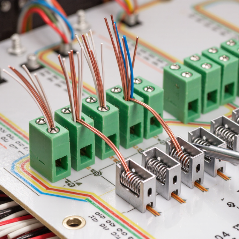
What PCB Terminal Blocks Are: Board-Mounted Connections for External Wiring
A PCB terminal block is a connector mounted directly on a printed circuit board, creating a removable connection for external wires. One side attaches to the board; the other accepts conductors through screw clamps, spring cages, or similar terminals. This arrangement is common in control panels, sensor units, and compact power modules. The wiring can be disconnected without desoldering the board.
Picture a small controller inside a plastic enclosure. Wires from a motor or sensor enter through the case and land in labeled terminal openings. The board carries those connections to its circuits. Simple, but details matter. Check the block’s pitch, wire range, rated current, and voltage against the design. Also confirm that its pins match the PCB footprint and that there is enough room for a screwdriver and cable bend. A neat-looking layout can still be awkward to service.
Screw-clamp versions are familiar and easy to inspect, though loose or overtightened screws can cause trouble. Spring-clamp types can speed up assembly, but the wire must be prepared as specified. Vibration, heat, and repeated maintenance may affect the best choice. There is no universal winner. Even labeling deserves attention; tiny markings can become hard to read after the enclosure is closed. A prototype check with the actual wire and housing often reveals what the drawing missed.
Why Choose PCB Terminal Blocks?
PCB terminal blocks provide board-mounted connection points for external wiring, making it possible to connect or disconnect wires without soldering them directly to the board.
Common PCB Terminal Block Pitch Options
These are common nominal pin-to-pin pitches, not a complete list. Choose a pitch that matches the PCB footprint, required electrical ratings, wire size, and available board space.
How Clamping Mechanisms Secure Conductors and Support Maintenance
A PCB terminal block is only as dependable as its contact with the conductor. Screw clamps apply pressure directly; spring clamps maintain contact as materials shift slightly with temperature changes. That matters near a warm power component, where repeated heating and cooling can loosen a marginal connection. A 2024 downtime analysis covering 500 large companies estimated losses at about 11% of annual revenue. Its findings underline why small, serviceable connections deserve attention. The True Cost of Downtime provides broad industrial context, not a guarantee that one terminal design prevents outages.
For maintenance, accessible clamping points make inspection and conductor replacement more practical. A technician can isolate the circuit, check for discoloration or damaged insulation, then verify the connection using the terminal’s specified method. With screw clamps, follow the stated torque; overtightening can damage conductors, while insufficient torque risks a weak contact. Spring clamps can speed wiring, but the correct conductor type and strip length still matter. Small details count. IEC 60947-7-1 sets requirements and tests for terminal blocks, including electrical and mechanical performance. Still, a compliant block cannot compensate for poor installation. I would not assume every vibration-prone assembly needs the same clamp; test the actual wiring, load, and service conditions.
Where PCB Terminal Blocks Serve: Controls, Power, and Instrumentation
In control cabinets, PCB terminal blocks connect sensors, switches, and relay circuits directly to a control board. Their screw or spring clamps make field wiring easier to inspect and replace. A technician can trace a labeled wire from a cabinet entry to a specific input without disturbing nearby connections. Small details matter. Choose a block that suits the conductor size, expected current, and available board space. Check the manufacturer’s ratings and PCB layout guidance before assembly; a compact footprint does not guarantee adequate electrical clearance or heat handling.
Power applications need closer attention to current, conductor temperature, and copper trace capacity. A terminal block cannot compensate for undersized PCB tracks. For instrumentation, stable connections help preserve low-level readings from pressure, temperature, and position sensors. Keep sensitive signal wiring apart from noisy switching lines where the layout allows. Noise matters here. Vibration, repeated maintenance, and the use of ferrules can also affect clamp choice and installation. It is tempting to treat terminal blocks as simple hardware, but that assumption can fail when wiring access is poor or torque is inconsistent. Review the finished assembly, not only the component datasheet.
IEC 60947-7-1 Scope: 0.2–300 mm², Up to 1,000 V AC or 1,500 V DC
Why Choose PCB Terminal Blocks for Your Projects?
Choosing a PCB terminal block means matching the connection to the real electrical load. IEC 60947-7-1 covers terminal blocks for copper conductors with rated cross-sections from 0.2 mm² to 300 mm². Its stated voltage limits reach 1,000 V AC or 1,500 V DC. These figures describe the standard’s scope, not a guarantee that every block supports every conductor size or voltage. That distinction matters.
For a compact control board, a small conductor may fit neatly, while a larger wire needs more space and secure clamping. Check the specific product’s ratings, permitted wire range, temperature limits, and mounting details. PCB copper thickness, spacing, enclosure airflow, and vibration also affect a dependable connection. A printed rating alone tells only part of the story. Inspect the datasheet, then consider the assembled equipment and its operating conditions. Even a well-chosen terminal can disappoint if the board runs hot or the wire is poorly prepared. That is easy to overlook.
Why Choose PCB Terminal Blocks for Your Projects? — IEC 60947-7-1 Scope: 0.2–300 mm², Up to 1,000 V AC or 1,500 V DC
A practical overview of terminal-block selection considerations for industrial and similar electrical applications.
| Selection Dimension | Relevant Information | Why It Matters to Your Project |
| Standard scope | IEC 60947-7-1 covers terminal blocks for copper conductors used in industrial and similar applications. | Provides a recognized framework for evaluating applicable terminal-block requirements. |
| Conductor cross-section | The standard’s stated scope includes conductor cross-sections from 0.2 mm² to 300 mm². | Confirm that the terminal block’s specified conductor range matches the conductors used in the design. |
| Voltage limits | Within the standard’s scope, rated voltage does not exceed 1,000 V AC or 1,500 V DC. | Check the individual product’s ratings and the installation’s electrical requirements; these limits are not ratings for every terminal block. |
| Conductor material | The standard applies to connections for copper conductors. | Verify conductor material compatibility before selecting a terminal block or planning a connection. |
| Connection method | Terminal blocks may use different clamping designs, including screw-type or screwless arrangements. | Choose a connection method suited to assembly, wiring, inspection, and maintenance needs. |
| Panel organization | Terminal blocks provide defined connection points for conductors in electrical assemblies. | Clearly arranged connections can make wiring easier to identify and support troubleshooting and servicing. |
| Installation compatibility | Mounting style, available space, conductor entry direction, and accessories vary by product. | Check dimensions, mounting arrangements, and accessory compatibility against the enclosure and assembly layout. |
| Current and temperature ratings | Allowable current and operating conditions depend on the specific terminal block and its installation requirements. | Use the product’s technical documentation to verify current capacity, temperature limits, and any applicable derating. |
Selection note: The IEC scope limits above describe the standard’s coverage; they do not replace the ratings and installation instructions for a specific terminal block.
How to Choose: Match Pitch, Wire Range, Ratings, and Operating Conditions
PCB terminal blocks make field wiring easier to connect, inspect, and replace without soldering each conductor directly to the board. Start by matching the pitch to the PCB layout and the space available for a screwdriver. Check the full block width, not just the distance between pins. Measure twice. Then compare the terminal’s wire range with the actual conductor, including any ferrule. A wire that fits loosely may pull free; one that is too large can be difficult to clamp securely. Follow the specified strip length and tightening torque, where provided.
Next, check current and voltage ratings against the circuit’s real operating conditions. Ratings can change with ambient temperature, wire size, and the number of loaded positions, so review the product data rather than relying on a headline value. The PCB traces and connectors must also support the expected load. For equipment exposed to vibration, dust, or heat, confirm that the terminal block is suitable for that environment. There is no perfect fit on paper: sample wires can behave differently from diagrams, and cramped enclosures can make access awkward. A quick prototype test can reveal problems before the board layout is fixed.

 24 Hour Service